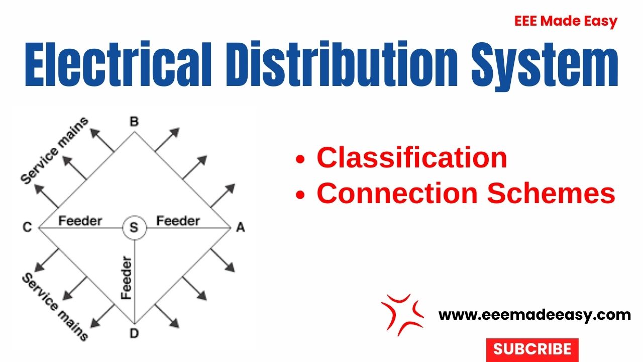
Electrical distribution system : The part of electrical system that distributes electrical power for local usage is known as electrical power distribution system.
Electrical power Distribution Systems
The part of electrical system that distributes electrical power for local usage is known as distribution system.
Join EEE Made Easy Whatsapp Channel
Components of Electrical distribution system
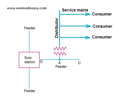
The distribution system is constituted by following three components;
- Feeders
- Distributors
- Service Mains
Feeders
Feeders: These are lines or conductors that connect major station to the area where the power is to be distributed. The current remains constant in feeders and the most important parameter is their current carrying capacity.
Distributors
Distributors: These are lines or conductors to which various consumers are connected. These distribute power among these consumers.
Service mains
Service mains: It is line or a cable that connects the distributor to the consumer’s terminal.
Read Also: Which IE rule is applicable to service mains?|Indian Electricity Rule
Classification of Distribution Systems
The distribution systems may be classified based on the following criteria:
- Type of construction
- Nature of current
- Scheme of connection
Type of construction
Type of construction: Overhead and underground distribution systems. Generally overhead
systems are cheaper and employed in preference.
However, underground cables are used where it is impractical or prohibition to use overhead lines.
Nature of current
Nature of current: AC and DC distribution system. The AC distribution system is universally
used because it is simpler and more economical.
Scheme of connection
Scheme of connection: Radial, ring main and inter-connected systems.
AC and DC Distribution Systems
The AC distribution system is for distribution for AC power, that is, AC voltage and current. It is further divided into the following two systems.
- Primary distribution system
- Secondary distribution system
Primary distribution system
Primary distribution system: For this system the general voltage level is 11kV, 6.6 kV and
3.3 kV, that is, higher than the voltage level used by the general consumers.
For economic considerations, this system is provided with three phase, three wire system.
Secondary distribution system
Secondary distribution system: In this case the distribution level is 230 V single phase or
415 V three phase four wire systems.
This voltage level is directly usable by the general consumers.
The DC distribution system is meant for distribution of DC voltages through the following two systems.
- Two-wire DC distribution system
- Three-wire DC distribution system
Two-wire DC distribution system
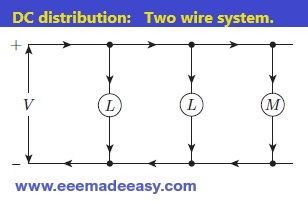
Two-wire DC distribution system: In this case the power is transmitted by two wires one positive (+) and then other negative (−).
The loads are connected between the two wires as shown in the Fig below.
Three-wire DC distribution system
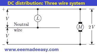
Three-wire DC distribution system: This system consists of two outer wires and one middle
wire which is earthed in the substation.
The voltage between the outer wires is twice the voltage between one line and earth. The configuration is shown in Fig below.
Distribution system Connection Schemes
The different connection schemes in distribution system are discussed as follows;
- Radial system
- Ring system
- Interconnected system
Radial system
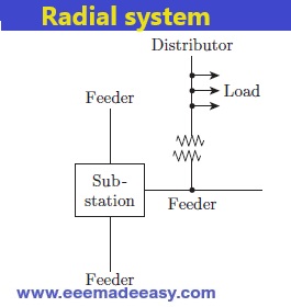
Radial system: In this system separate feeders radiate from a single substation and feed the distributor one end only.
This system is used when the power is generated at low voltage and the substation
is located at the centre of the load.
Radial system Drawbacks
The drawbacks of the Radial system are:
- Consumers are dependent only on single feeder and distributor, so in event of a fault, the power supply will be cut-off completely.
- The distributor end nearest to the feeding point is heavily loaded.
- The consumers at the distant end of the distributor (away from the feeder) will be impacted by voltage fluctuations as the load on the distributor changes.
Ring system
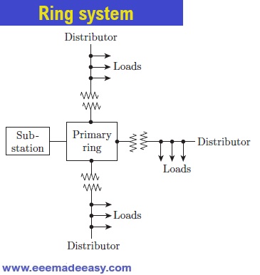
Ring system: In this system, two feeders are used to supply power to single substation at both ends.
Thus, a loop circuit starts from the substation bus bars, covers the area of supply by forming a loop and returns to the substation.
The disadvantages of the radial system, that is voltage fluctuation and low reliability, are thus overcome.
Since the distributor is fed by two feeders, in event of a fault at one end, the power continues to be supplied.
Interconnected system
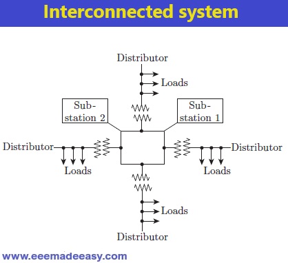
Interconnected system: In this system, the feeder ring receives power from two or more generating substations.
This increases the reliability of the supply and increases efficiency of the system.
An area, during the peak load hours, can be fed with feeder from alternate generating substation.
The three connection schemes, for AC distribution system are shown in Figures given above.
Read more on Power System
- Electrical Power System Problems and Solutions
- Three Phase System|Advantages of Three Phase System
- [MCQ Set 3]Electrical Power Generation, Transmission and Distribution MCQ Questions
- Electrical power Generation
- Wind Energy Power Plants|Wind Power Generation|Wind Mill Working
- Transmission tower design|Electrical tower design
- Types of Transmission Towers|Electrical Tower Types
- Transmission structures|Transmission towers and Transmission Poles|Electric Tower
- Parts of a Power transmission line and Transmission tower|Transmission tower parts
- Steam power plant Layout|General layout of Steam Power Station
- Lightning Arrester|ESE Lightning Arrester & Conventional Iightning Arrester
- [MCQ Set 2]Electrical Power Generation, Transmission and Distribution MCQ Questions
- [MCQ Set 1]Electrical Power Generation, Transmission and Distribution MCQ Questions
- Electrical power Generation
- Steam power plants|Steam power generator Plant|Thermal Power Plants
- Comparison of ac and dc transmission
- Types of Insulators in Transmission lines
- Skin Effect and Proximity Effect
- Electrical Distribution System
Latest Posts in EEE Made Easy
- Environment MCQ for RRB JE CBT 2|Objective Questions Environment for Competitive Exams
- RRB JE CBT 2 Computer Awareness Book Arihant|Objective Computer Awareness Book 2025
- RRB JE CBT 2 Exam Date 2025 Postponed|RRB JE CBT 2 Exam Date
- [PDF]RRB JE Result 03/2024 Cut off, Selected no of candidates for all regions
- [PDF]Final Answer Key Junior Instructor Mechanic Agricultural Machinery|643/2023 Solved Question paper
- Acoustics MCQs|Industries Extension officer|IEO 2025
- LASER MCQs| Industries Extension officer|IEO 2025
