References :
1 General layout of Steam Power Station|Steam power plant parts
What is a Rankine cycle?
Rankine cycle is the idealized cycle for steam power plants.
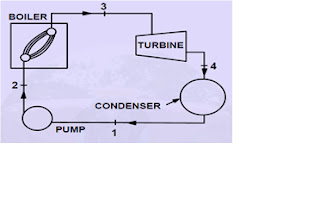
This cycle is shown on p-v,T-v, h-s, diagram It consists of following processes:
Process 1-2: Water from the condenser at low pressure is pumped into the boiler at high pressure. This process is reversible adiabatic.
Process 2-3: Water is converted into steam at constant pressure by the addition of heat in the boiler.
Process 3-4: Reversible adiabatic expansion of steam in the steam turbine.
Process 4-1: Constant pressure heat rejection in the condenser to convert condensate in to water.
Ideal Rankine cycle
In an ideal Rankine cycle the pump and turbine would be isentropic, i.e., the pump and turbine would generate no entropy and hence maximize the net work output. Processes 1-2 and 3-4 would be represented by vertical lines on the T-S diagram and more closely resemble that of the Carnot cycle.
The Rankine cycle shown here prevents the vapour ending up in the superheat region after the expansion in the turbine, which reduces the energy removed by the condensers.
The p-v diagram, h-s diagram and T-s diagram are given below.
The efficiency of ideal Rankine cycle is not achieved, which is a reference value of an ideal steam power plant.
In a real power plant cycle (the name ‘Rankine’ cycle used only for the ideal cycle), the compression by the pump and the expansion in the turbine are not isentropic.
In other words, these processes are non-reversible and entropy is increased during the two processes. This somewhat increases the power required by the pump and decreases the power generated by the turbine.
In particular the efficiency of the steam turbine will be limited by water droplet formation. As the water condenses, water droplets hit the turbine blades at high speed causing pitting and erosion, gradually decreasing the life of turbine blades and efficiency of the turbine.
The easiest way to overcome this problem is by superheating the steam.
On the T-s diagram above, state 3 is above a two phase region of steam and water so after expansion the steam will be very wet.
By superheating, state 3 will move to the right of the diagram and hence produce a drier steam after expansion.
Due to the pressure drops in the passages and the irreversibilities in various components, the ideal Rankine cycle deviates from the actual Rankine cycle.
The above fig shows the actual Rankine cycle where, 1-21 is due to the irreversible process in feed pump and 3-41 is due to the turbine irreversibility.
The actual efficiency of steam power plant, by replacing the enthalpies h2 and h4 by h21and h41 will be,
The actual thermal efficiency, should be made as close as possible to ideal thermal efficiency.
The thermal efficiency of a steam power plant can be increased by following ways;
a)Increase in initial steam pressure.
b)Increase in initial steam temperature.
c)Increase in condenser vaccum.
d)Regenerative feed water heating.
e)By reheating.
f)By use of economizer.
Reheat cycle (Rankine cycle with reheat)
Reheating is a process by which steam at the end of expansion in turbine stages is taken out to boiler or reheater for resuperheating.
This reheated steam does more work in the next stage of turbine and increases the thermal efficiency of the plant.
The fig. Given below shows a Rankine cycle with single reheat without any feed water heating.
The purpose of a reheating cycle is to remove the moisture carried by the steam at the final stages of the expansion process.
In this variation, two turbines work in series. The first accepts vapour from the boiler at high pressure.
After the vapour has passed through the first turbine, it re-enters the boiler and is reheated before passing through a second, lower-pressure, turbine.
The reheat temperatures are very close or equal to the inlet temperatures, whereas the optimum reheat pressure needed is only one fourth of the original boiler pressure.
Among other advantages, this prevents the vapour from condensing during its expansion and thereby damaging the turbine blades, and improves the efficiency of the cycle, given that more of the heat flow into the cycle occurs at higher temperature.
The reheat cycle was first introduced in the 1920s,but was not operational for long due to technical difficulties. In the [1940s] it was reintroduced with the increasing manufacture of high-pressure boilers, and eventually double reheating was introduced in the 1950s.
The idea behind double reheating is to increase the average temperature. It was observed that more than two stages of reheating are unnecessary, since the next stage increases the cycle efficiency only half as much as the preceding stage.
Today, double reheating is commonly used in power plants that operate under supercritical pressure.
The constant pressure line 5-6 shows the reheat process. If QR is the heat supplied during the reheating, the total heat supplied will be
Therefore, the thermal efficiency of plant with reheat will be given by,
The efficiency of the cycle depends upon the reheat pressure.
There is an optimum value of reheat pressure.
At first reheat, it is 0.2 to 0.25 times the initial pressure of steam whereas for next reheat, it is 0.2 to 0.25 times the first reheat pressure of steam and so on.
Regenerative cycle
The heating of feed water by steam extracted at various points while sending it to the boiler is termed as regenerative heating.
Thermal efficiency can be increased by 10% and therefore it is universally used in all steam power plants.
The large no. of heaters makes the system design more complicated and leads to considerable loss of pressure.
The no. of heaters employed in large steam plants is 6 to 10 with a final feed water temperature of about 2850C.
Heat rate
It is a measure of the performance of the power plant in converting heat to useful output.
It is defined as the no. of heat units required to develop unit power output in an hour.
The heat rate decreases with the increase in thermal efficiency.
- Environment MCQ for RRB JE CBT 2|Objective Questions Environment for Competitive Exams
- RRB JE CBT 2 Computer Awareness Book Arihant|Objective Computer Awareness Book 2025
- RRB JE CBT 2 Exam Date 2025 Postponed|RRB JE CBT 2 Exam Date
- [PDF]RRB JE Result 03/2024 Cut off, Selected no of candidates for all regions
- [PDF]Final Answer Key Junior Instructor Mechanic Agricultural Machinery|643/2023 Solved Question paper
- Acoustics MCQs|Industries Extension officer|IEO 2025
- LASER MCQs| Industries Extension officer|IEO 2025
- Practical Types of Capacitors
- [PDF] Syllabus JUNIOR INSTRUCTOR MECHANIC AGRICULTURAL MACHINERY|643/2023 Syllabus Kerala PSC
- [PDF] Syllabus JUNIOR INSTRUCTOR WOOD WORK TECHNICIAN|674/2023 Syllabus Kerala PSC
- [PDF] Syllabus JUNIOR INSTRUCTOR MECHANIC CONSUMER ELECTRONIC APPLIANCES|670/2023 Syllabus Kerala PSC
- [PDF] Junior Instructor Hospital Housekeeping| 646/2023 syllabus Kerala PSC


